MEP-113A 15 kW 400 Hz Diesel Generator
NSN: 6115-00-118-1244
TM numbers:
ARMY TM 9-6115-464-12
AIR FORCE TO 35C2-3-445-1
NAVY NAVFACP-8-624-12
ARMY TM 9-6115-464-12
AIR FORCE TO 35C2-3-445-1
NAVY NAVFACP-8-624-12
Expanded Description:
MEP-113A 15 KW 400 HZ GENERATOR
MEP-113A 15 KW 400 HZ GENERATOR
Additional Notes:
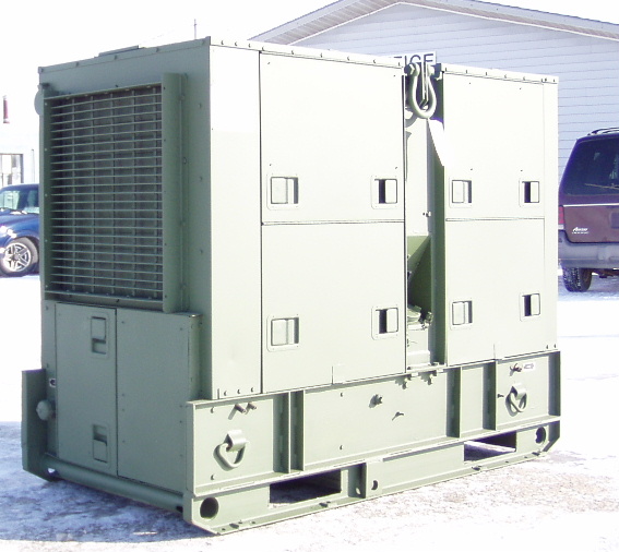
400hz or "HIGH CYCLE" USED MAINLY IN THE AIRCRAFT INDUSTRY. Generator sets, models MEP-004A, MEP-103A, and MEP-113A (Figure 1-1 and Figure 1-3)
are fully enclosed, self-contained, skid mounted, portable units. They are equipped with controls, instruments,
and accessories necessary for operation as single unit or in parallel with one or more units of the same class
and mode. Each set is equipped with engine oil pan heating elements and necessary connections for field
installation of winterization kits. Lifting devises for hoisting the generator set are located at the top of the lifting
frame and center support assembly. Tubular cross members, that will accept a chain, have been provided
at the front and rear of the skid base assembly to permit towing for short distances. Mobility of the units may
be obtained by mounting on trailers or equipping with a wheel mounting kit. To extend the capability of the
generator sets, they have also been designed to accept and operate with the following optional kits:
(1) Fuel Burning Winterization Kit (paragraph 5-3).
(2) Electric Winterization Kit (paragraph 5-9).
(3) Wheel Mounting Kit (paragraph 5-15)
(4) Load Bank Kit (paragraph 5-20).
(5) Applications Kit (paragraph 5-26).
(6) Acoustic Suppression Kit (paragraphs 2-27 and 5-29).
(7) Automatic Transfer Panel 50/60 Hz. Monitors 50/60 Hz primary power and automatically starts and transfers
the load to a standby generator set in the event of abnormal primary power fluctuation or failure. Continues
sensing primary power and upon satisfactory resumption, will return the load to the primary power
source, shut-off and recycle the generator set to a standby condition. (See Appendix A for manual.)
(8) Automatic Transfer Panel 400 Hz. Monitors 400 Hz power and automatically starts and transfers the
load from an operating 400 Hz generator set to a like standby set in the event the operating set load
contactor opens due to a faulty condition. (See Appendix A for manual.)
(9) Remote Control Box. Permits starling and stopping of the generator set from a remote location. (See
Appendix A for manual.)
(10) Auxiliary Fuel Burning Winterization. Provides adependable external source of battery power for starting
of the generator set in ambient temperatures from -25°F to -65°F. (See Appendix A for manual.)
(11) Auxiliary Electric Winterization. Provides a dependable external source of battery power for starting
a generator set in ambient temperatures from -25°F to -65°F. (See Appendix A for manual.)
(12) Acoustic Suppression Kit. Provides noise suppression to lower sound to 70 dB(A) at 7 meters.
b.
c.
d.
e.
f.
Engine. Power source of the generator set is a four cylinder, four cycle, fuel injected, Iiquid-cooled diesel engine.
The engine electrical system contains a cranking motor, two 12-volt batteries in series, and a battery
charging alternator with integral rectifier and voltage regulator. The engine is also equipped with a fuel filter
and strainer assembly, a secondary fuel filter, a lubricating oil filter, and an air cleaner. Cooling water is circulated
through the engine by a water pump. Safety devices automatically stop the engine during conditions
of high coolant temperature, low oil pressure, no fuel, over-speed, or over-voltage.
Generators. The alternating current generators are single bearing, drip-proof, synchronous, brushless,
three phase, fan cooled generators. Rated voltages are maintained by excitation of the generator-exciter
field by a static exciter mounted on the relay table. The cooling fan, located at the front of the generator,
impels cooling air which enters the generator and passes over the windings. Safety devices are provided
to protect the generator in the event of short circuit, overload, under-voltage, under-frequency, reverse
power, and over-voltage.
Control Cubicle. The generator set control cubicle is located at the rear top of the generator set and contains
controls and instruments for operating the engine and the generator. The control panel is grounded to protect
the operator from electrical shock in the event of a short in the equipment. The generator section of
the control panel contains meters for monitoring generator output, adjusting knobs for increasing and decreasing
frequency (Class 1 only) and voltage, and a circuit breaker switch for interrupting all output from
the generator set. Also included on the generator control panel are an operations switch and synchronizing
lights for operating the set as a single unit or in parallel with other units. The engine section of the control
panel contains switches for priming, starting, and stopping the engine and meters for monitoring set fuel
level, oil pressure, and coolant temperature. Also included is an ammeter for the battery charging alternator.
Electric/Electro-HydrauIic Governing System (Precise Sets Only). The electric governing system senses
speed and load electrically and provides the controls and load responses necessary for effective single
unit or parallel operation. The system consists of a rheostat for frequency adjustment, a load measuring
unit for sensing load changes, and a governor control unit which signals the actuator for rapid governor
response. The MEP-103A and some MEP-113A generator sets use an electro-hydraulic governing system,
which includes a hydraulic actuator, a hydraulic pump, and a hydraulic sump. Other MEP-113A sets
use an electric-magnetic actuator.
Mechanical Governing System (Utility Sets Only). The mechanical governing system provides the controls
and load responses necessary for efficient single unit, or parallel, operation of utility generator sets. Engine
rpm and set frequency are controlled by the mechanical governor, an integral part of the fuel injection pump,
which actuates the fuel metering valve. Adjustment of engine rpm and set frequency is accomplished by
use of a manual speed control located adjacent to the control cubicle. This control is a knob type device
which permits rapid frequency adjustment, locking in any position, and vernier adjustment for finer control.